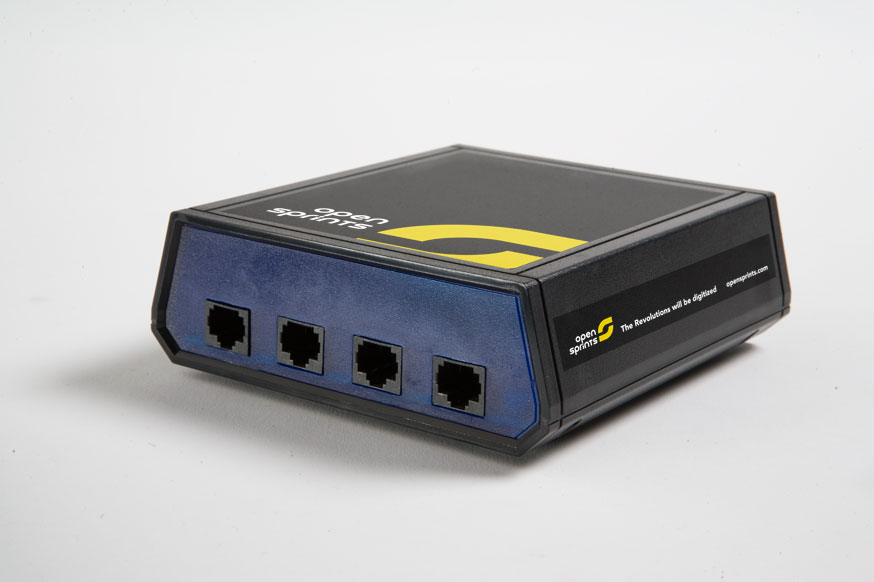
OpenSprints Hub Assembly
Not to be confused with a Network Hub.
The OpenSprints Hub, is basically an Arduino piggyback board that provides a safe and convenient interconnect for the sensors. Ethernet cables are used to connect the sensors to the Arduino. Extensive prototyping area on our green board design allows for ease of extending the functionality of the system.
Assembly
- TOP: Press in four RJ45 Jacks, they should snap into place.


BOTTOM: RJ45 Jacks pressed into place.
- Solder in RJ45 Jacks.

BOTTOM: RJ45 Jacks soldered into place.
- Install Power LED (and resistor). Colors of a 100 ohm Resistor, brown on one end, gold on the other.
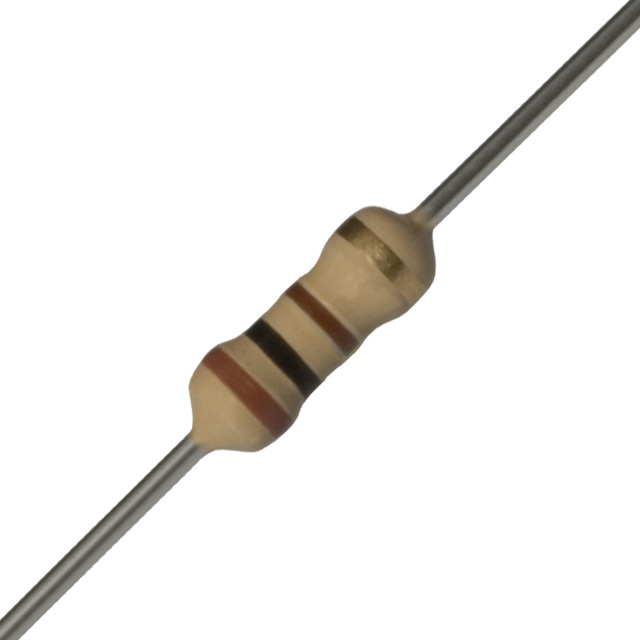
TOP: White power LED goes in D1, direction DOES matter. 100 ohm resistor goes in R1, direction doesn't matter.

- Get your parts ready to install the Arduino Board.

- Install two standoffs. TOP: Hold countersunk screw from bottom.

TOP: Thread on standoffs.
BOTTOM: Tighten standoffs from the bottom with the countersunk screws. DO NOT OVER TIGHTEN. This is not the 'Jesus Nut' on your helicopter.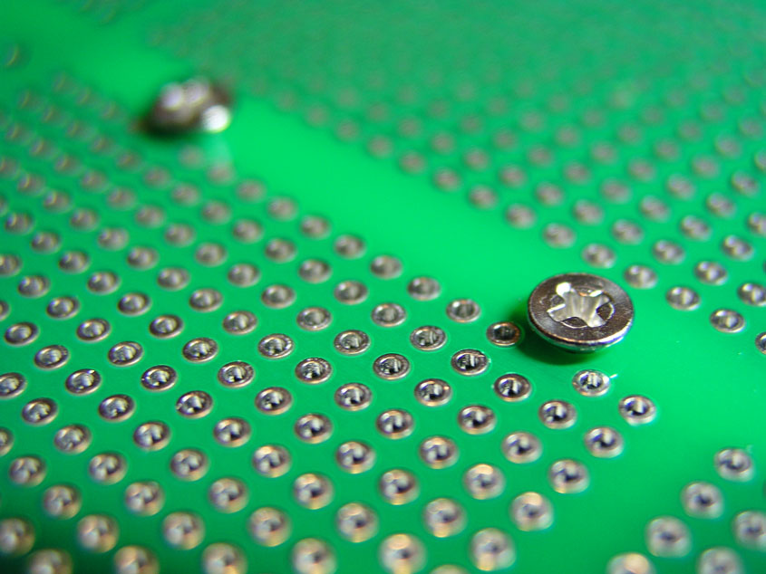
- Install male headers. If need be, break male headers into two 6 pin and two 8 pin sections.
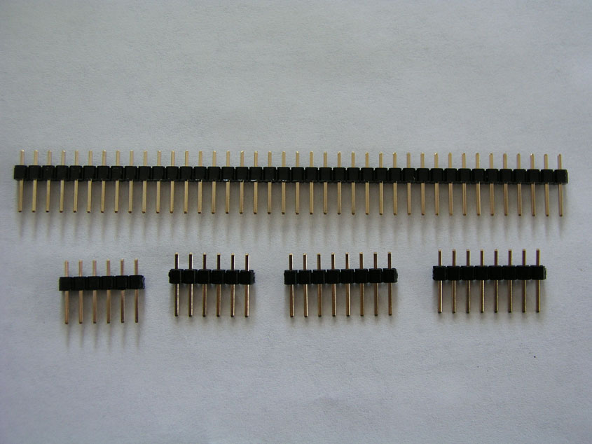
TOP: Insert the shorter legs of the male headers into the PCB which means the longer ones are pointing up. DO NOT SOLDER YET.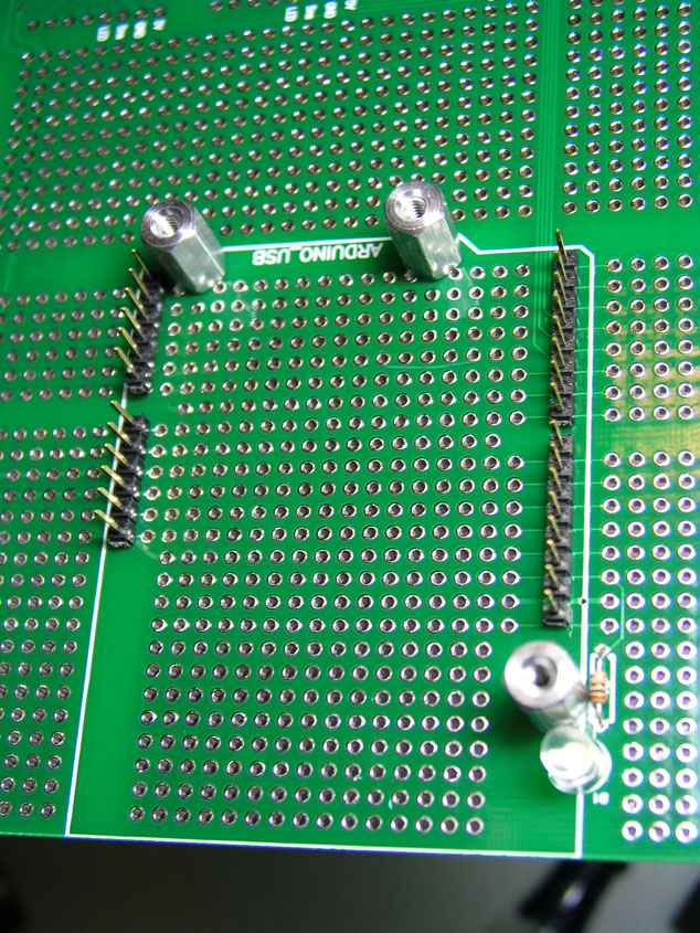
TOP: Place the Arduino.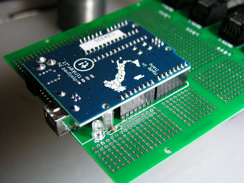
NOTE: There are extra headers on the Uno, that is ok.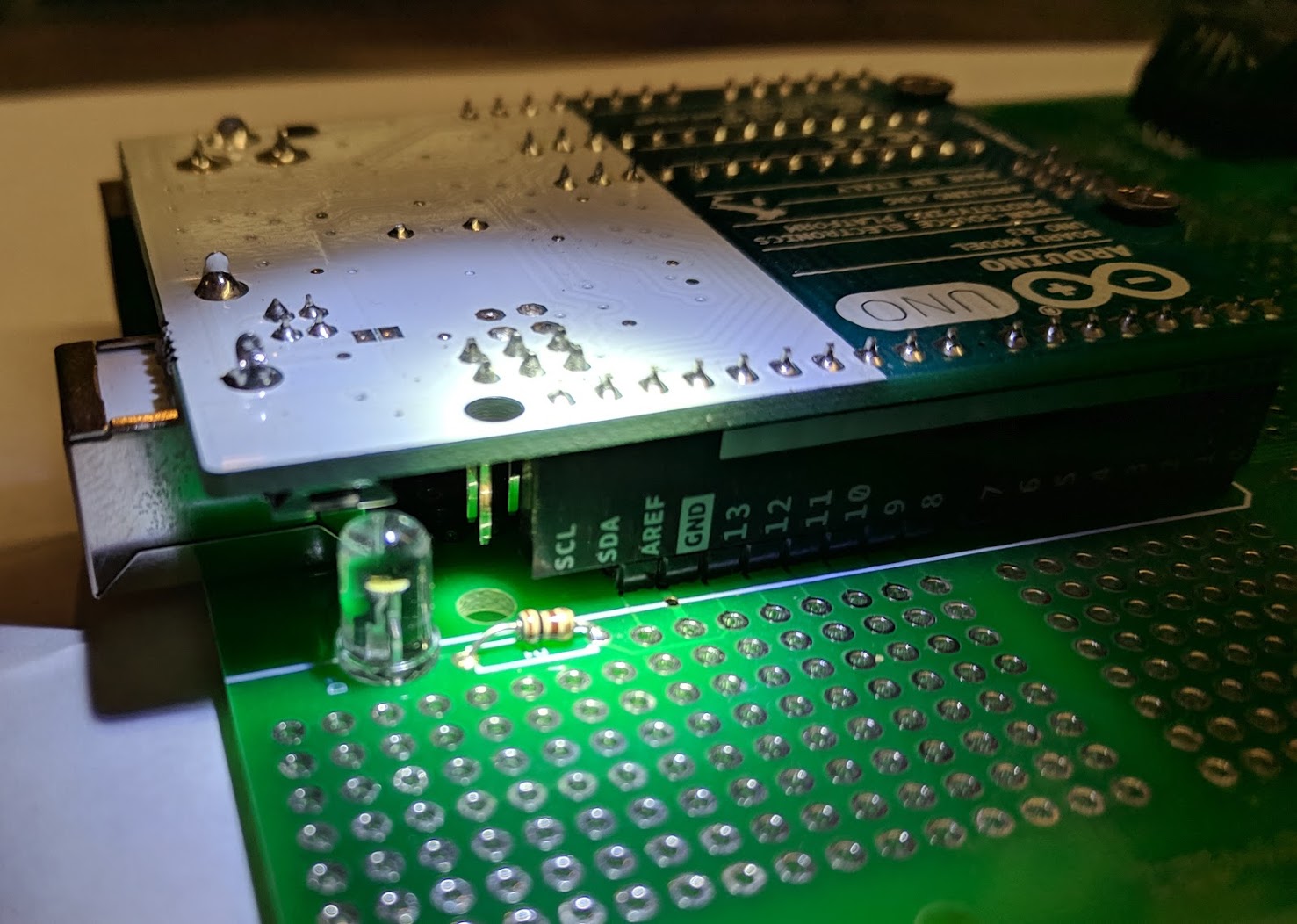
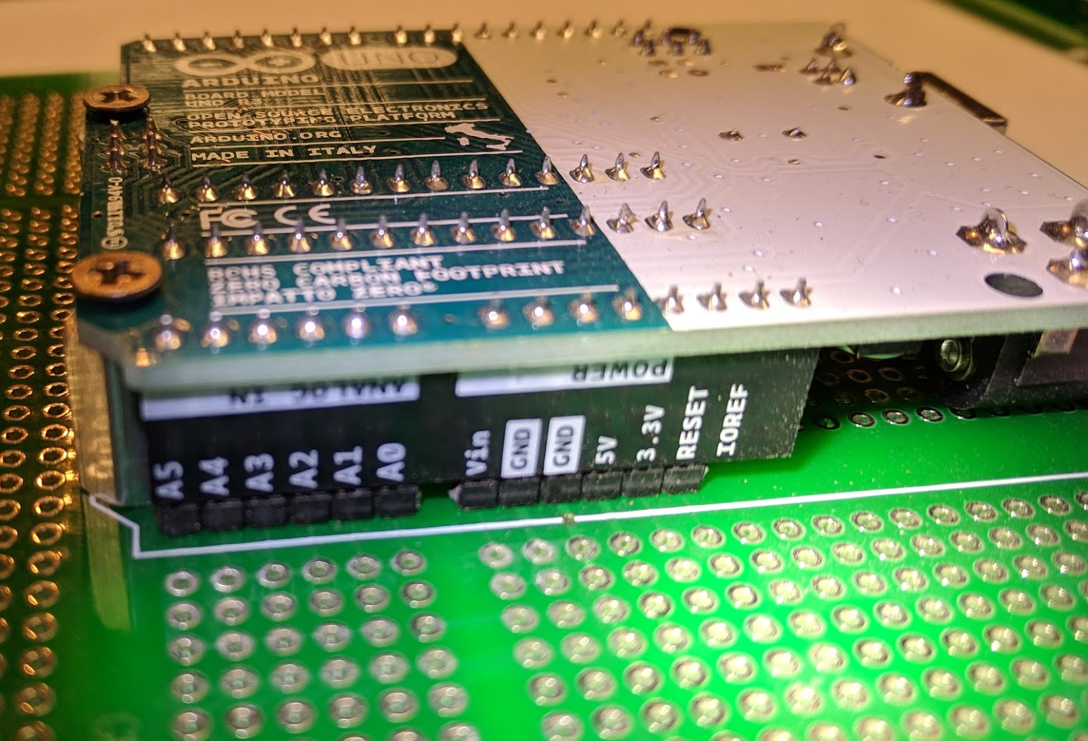
TOP: Screw Arduino into place with the remaining 3 countersunk screws. AGAIN, DO NOT OVER TIGHTEN. Let us repeat, this is not the Jesus nut on your helicopter.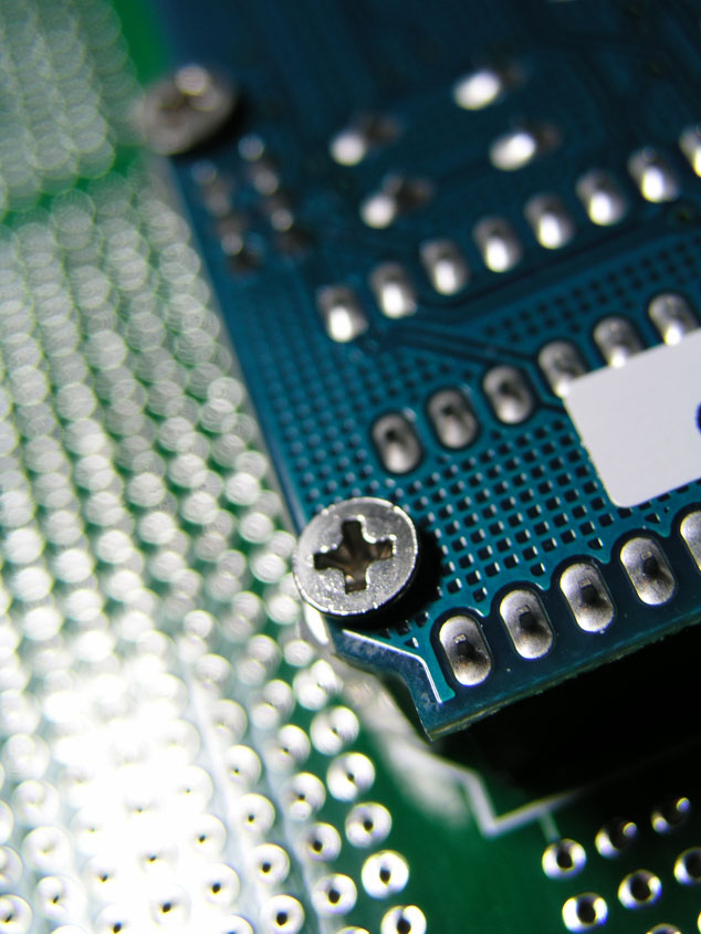
BOTTOM: Now that the Arduino is holding the headers straight and in place, solder the headers from the bottom of the PCB. The breakaway headers are very sensitive to heat. When soldering in the pins, work fast or the plastic casing will melt around the pin.
- Get the rest of your parts ready.
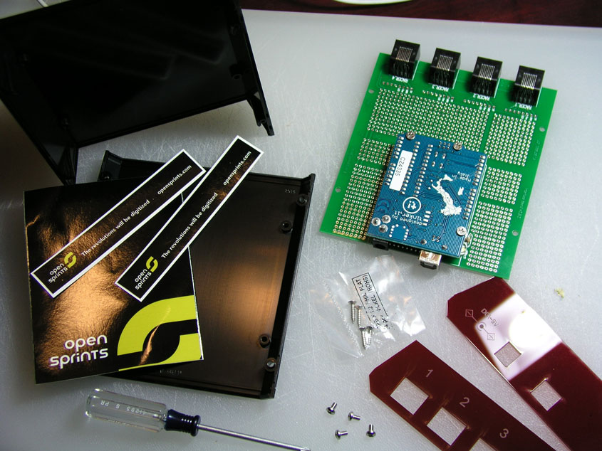
- Install End Panels. Attach end panels and set everything into the bottom of the case. NOTE: It is almost impossible to put in the end panels on AFTER you screw the PCB in place.

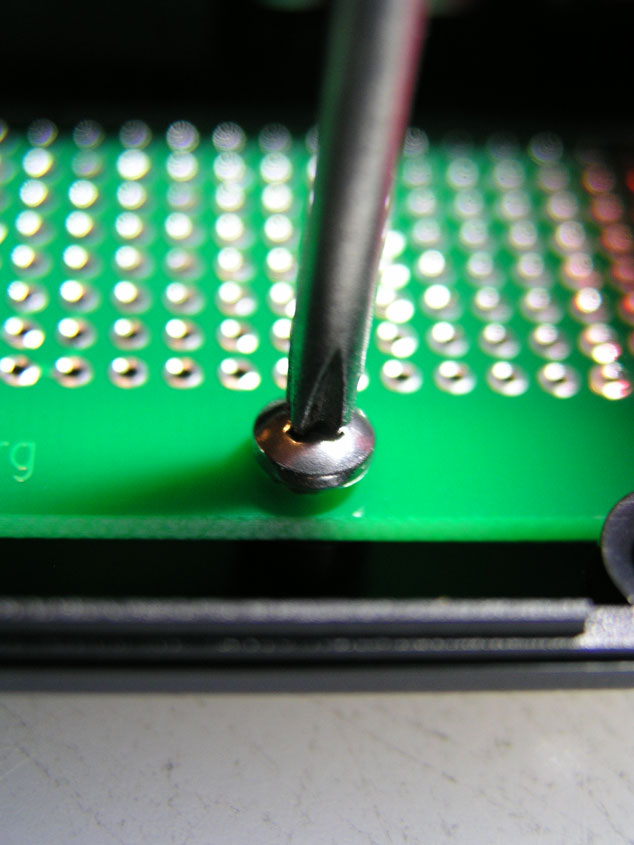
- Screw PCB to case. TOP: Screw interface board to bottom of the case using the pan head screws.
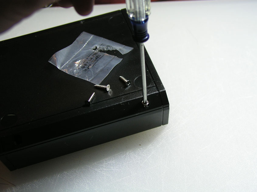
- Screw Case Together. BOTTOM: Screw case together while upside down using the screws that came with the enclosure. They are usually in a little baggy.
- Install Adhesive Feet. BOTTOM: Note the indentations on the bottom of the case.

BOTTOM: The indentations are where the adhesive feet go.
BOTTOM: There are four adhesive feet.
- Naked case. Something is missing... Install Stickers!

Stickers! Now you are ready for the Firmware update.
Tips & Tricks
If you didn't buy a kit directly from OpenSprints, but you are using these instructions, these tips will help.
- Install blinker LED with anode connected to Arduino pin 13, and a resistor connected between the LED's cathode and GND. A good resistor value for white, blue, or green LEDs is 100 Ohms. A good resistor value for red, yellow, or orange LEDs is 220 Ohms. The newest version of the interface PCB has pads for the LED and resistor.
- Cutting your own End Panels. Cut the face plates of the project box to make openings for the USB jack and the RJ45 jack(s), and slide the face plates into place on the project box. This will add much needed structural support to the enclosure in the event it is stepped on, however you can omit this step. Here are the CAD drawings for the parts if you wanted to get them professionally cut:
- Enclosure: Click on the User Prints tab
- Ethernet Jack: Click on the Product Drawings
- Arduino Board: Schematic & Reference Design
Updating Firmware
Update Arduino with OpenSprints Firmware
Troubleshooting
